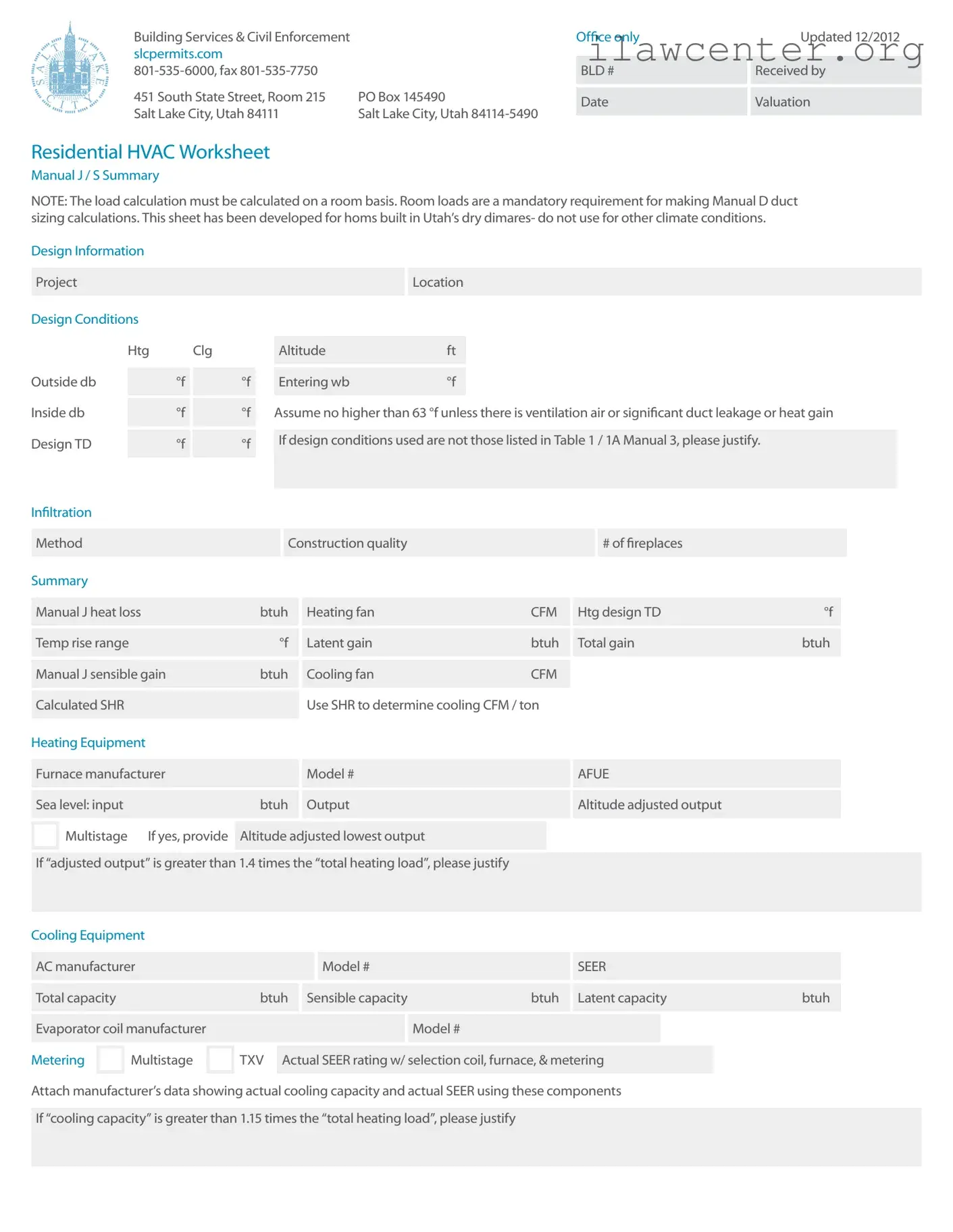
Manual J / S Summary
Instructions
The load information asked for on the
summary must be taken from the actual
load calculation completed on the project.
Project
Identify project name, lot number- information
that matches the plan submitted.
Location
The city or town must be reasonably close
to actual location. Software used may not
have the specic location in the database.
Outside Dry Bulb, Inside Dry Bulb
Temperature data should be from Table 1 or
Table 1A of ACCA Manual J. It is understood
that there may be situations where a slight
adjustment to this values is necessary. For
example; there may be areas in the Salt
Lake Valley where the low temperature is
historically lower than the airport temperature.
If values are adjusted- please justify the
adjustment. Provide both heating (htg) and
cooling (clg) design temperatures. If inside
or outside design conditions listed are not
the same values listed in Manual J, explain
why the different values were used.
Entering WB
The entering wet-bulb represents the
default value wet-bulb temperature across
the evaporator coil. This will typically be
63 °f (75 °f dry bulb) relative humidity). A
higher wb temperature will result from duct
leakage, un-insulated duct or ventilation
air- any condition that raises the return
air temperature. Use this wb temperature
when selecting cooling condenser from
manufacturer’s comprehensive data.
Design TD
TD: the temperature difference between
inside and outside design temperatures.
Inltration
Inltration calculations are based on the
Construction Quality. Version 7 of Manual ] uses
Best, Average or Poor to evaluate Inltration.
Version 8AE uses Tight, Semi-Tight, Average,
Semi-Loose and Loose to evaluate. Version 8
goes into very specic detail for a more accurate
number. Note method used on summary. Open
rebox replaces that draw air from inside the
home must be included, even if there is a 4”
‘combustion air’ ex bring air into the replace.
Sealed, direct vent type replaces should
not be counted. Methods include: Simplied
/ Default Method- taken from Table 5A;
Component Leakage Area Method- calculating
inltration based on individual leakage points
taken from Table 5C of Manual J8; or Blower
Door Method, where the actual leakage is
based on a blower door test on the home.
Manual J Heat Loss
This is the whole house winter heat loss taken
directly from the completed attached Load
Calculation. Load must account for all factors
such as loss building components as well as loss
through inltration, ventilation, and duct losses.
Heating Fan
Heating airow typically may be lower than
cooling cfm. Adjusted to insure the temperature
rise across the heat exchanger falls within the
range specied by the manufacturer. Software
will often do this calculation and provide a
correct heating cfm. See Manual S Section 2-6 -
Rise (°f) = Output Capacity ÷ (1.1 x heating cfm)
Manufacturer’s Temperature Rise Range
Range taken from manufacturer’s
performance data. Various manufacturers
may certify ranges from 20 - 70 °f.
Manual J — Sensible Gain
The whole house summer heat gain taken
directly from the completed attached Load
Calculation. Load must account for all factors
including gain through building components,
solar gain, inltration, ventilation and
ducts. Also includes the sensible internal
gains from appliances and people.
Manual 3 — Latent Gain
The gains due to moisture in the air. Large latent
load are typically from moisture migration
into the home from outside in humid climates.
People, cooking, plants, bathing and laundry
washing can all add to the latent load in a home.
Total Gain
The combined total of the sensible and latent
gain. May be referred to as Total Cooling Load.
SHR- Sensible Heat Ratio
Use to determine Cooling cfm per ton.
The ratio of sensible heat gain to total heat
gain. SHR = Sensible Heat Gain ÷ Total
Heat Gain. Recommended air ows: If SHR
is below 0.80 select 350 cfm / ton; if SHR
is between 0.80 & 0.85 select 400 cfm; if
SHR is greater than 0.85, select 450 cfm
/ ton. Note: This cfm is not the nal cfm;
additional adjustment may be required for
Altitude. See next item- Cooling Fan.
Cooling Fan
Software used to perform the calculation
will typically provide a minimum cfm
based on the minimum required size of the
equipment. This number may be adjusted
to meet specic requirements of the home.
Heating and Cooling CFM may or may not
be the same. The cooling CFM should be
around 450 CFM per ton of cooling in Utah’s
dry climates. For higher altitudes, CFM must
be adjust up as detailed in ACCA / ANSI
Manual S. Mountain location should expect
Cooling CFM at 500 CFM per ton and higher.
HEATING
Equipment
List specic equipment to be used. This
information is not required on the Load
Calculation documents, however it must
be provided here to verify equipment
sizing against calculated loads.
AFUE
The AFUE (Annual Fuel Utilization Efciency)
listed here will be compared to that listed on
plans and on energy compliance documents
(RES check or other). It must also match the
equipment actually installed in the home.
Sea Level Input
The listed input on the furnace label
and in manufacturers’ documentation.
Input represents the total amount
of heat in the gas at sea level.
Output
The amount a heat available for discharge
into the conditioned space. The input less any
vent or stack losses, or heat that is carried out
with the products of combustion. May be take
from manufacturer’s performance data or
calculated using input and furnace efciency.
Altitude Adjusted Output
This number is the actual output that will be
attained after the furnace has been adjusted
for efciency and de-rated for altitude (typically
4% for every 1000’ above sea-level, however
2% /1000’ for many 90+ efcient furnaces).
Some manufacturers may have different
requirements- adjustments should be made
per their requirements. Calculations should be
attached. Example: 80,000 input 91% efcient
furnace in Salt Lake, with manufacturers’
installation instructions specifying 4% /
1000’. 80,000 x .91 x .83 = 60,424 btuh.
Multi-Stage Furnace
Multi-stage and modulating equipment is now
available. When comparing to heating load
calculated, use the maximum adjusted output
to verify the furnace is large enough and the
lowest output to insure it is not too large.
Size Justication
Example: If the Total Heating Load = 29954
btuh. A furnace with an adjusted output larger
than 45,000 btuh (29954 x 1.5 = 44931) would
require an explanation justifying the size.
COOLING
Equipment
List specic equipment to be used. Provide
manufacturers comprehensive data for
furnace, furnace blower and condenser, with
capacities at design conditions highlighted.
Condenser SEER
This SEER (Seasonal Energy Efciency Ratio) is
the listed SEER for this model series, not the
exact SEER with components used this system.