Megger Test PDF Template

Megger Test PDF Template

The Megger Test form is a crucial document used to record the results of insulation resistance testing in electrical systems. It includes essential details such as project number, station, date, and various voltage readings between phases and neutral. Completing this form accurately ensures compliance and safety in electrical installations; click the button below to fill out the form.

Article Guide

The Megger Test form serves as a critical tool in the evaluation of electrical insulation and system integrity across various projects. This document is structured to capture essential information, including the project number, station details, and the date of testing, which are crucial for tracking and reference purposes. Each test is associated with specific feeder panel identification and circuit numbers, ensuring that data is accurately linked to the correct electrical systems. Voltage measurements across different phases, such as Phase A to Phase B and Phase A to Phase C, are documented, along with readings to neutral and ground. These measurements provide insight into the electrical performance and safety of the system. Additionally, the form requires signatures from key personnel, including the RPSC field engineer, project engineer or designee, and the electrical foreman, which adds a layer of accountability and oversight. The inclusion of a designated NSF representative or inspector further enhances the reliability of the test results. Overall, the Megger Test form is an indispensable component in maintaining electrical safety and compliance in various settings, particularly in remote locations such as McMurdo, Palmer, and the South Pole.

Megger Test Preview

MEGGER TEST REPORT
EN-MPS-725e FEMC / RPSC Paget 1 of 1 Revision 1 11/16//06 Approved by Wayne L. Cornell
PROJECT NUMBER
DATE (M/D/YYYY)
PROJECT
STATION
MCMURDO PALMER SOUTH POLE
FEEDER PANEL
IDENTIFICATION
CIRCUIT
NUMBER/FEEDER
NUMBER
VOLTS/
PHASE/
CYCLES
PHASE “A
TO
PHASE “B”
PHASE “A
TO
PHASE “C”
PHASE “B”
TO
PHASE “C”
PHASE “A
TO
NEUTRAL
PHASE “B”
TO
NEUTRAL
PHASE “C”
TO
NEUTRAL
PHASE “A
TO GROUND
CONDUCTOR
PHASE “B”
TO GROUND
CONDUCTOR
PHASE “C”
TO GROUND
CONDUCTOR
RPSC FIELD ENGINEER
PROJECT ENGINEER/DESIGNEE:
DATE
RPSC ELECTRICAL FOREMAN:
DATE
NSF REP/TITLE II INSPECTOR:
DATE

File Properties

Fact Name Description
Project Number This unique identifier is essential for tracking the specific project associated with the Megger test.
Project Station Indicates the location where the Megger test is conducted, such as McMurdo, Palmer, or South Pole.
Date The date of the test is recorded in the format M/D/YYYY, ensuring clarity and consistency.
Feeder Panel Identification This identifies the specific electrical panel being tested, which is crucial for maintenance records.
Circuit Number/Feeder Number Each circuit or feeder has a designated number, aiding in the organization and safety of electrical systems.
Voltage and Phase Information Details about volts, phases, and cycles are documented to assess the electrical system's performance.
Ground Conductor Testing Tests are performed between various phases and ground conductors to ensure safety and compliance.
Field Engineer and Project Engineer Signatures from the RPSC field engineer and project engineer/designee validate the accuracy of the report.
NSF Rep/Title II Inspector The inspection sign-off confirms that the Megger test meets the required standards and regulations.

Instructions on Utilizing Megger Test

Filling out the Megger Test form requires careful attention to detail. Each section of the form must be completed accurately to ensure that all necessary information is recorded. Below are the steps to guide you through the process of filling out the form.

  1. Locate the PROJECT NUMBER section and enter the appropriate project number.
  2. Fill in the PROJECT STATION field with one of the following: MCMURDO, PALMER, or SOUTH POLE.
  3. Enter the DATE in the format M/D/YYYY.
  4. Identify the FEEDER PANEL IDENTIFICATION and write it down.
  5. In the CIRCUIT NUMBER/FEEDER NUMBER section, input the relevant number.
  6. Record the VOLTS/PHASE/CYCLES information as applicable.
  7. Measure and document the voltage readings for the following pairs:
    • PHASE “A” TO PHASE “B”
    • PHASE “A” TO PHASE “C”
    • PHASE “B” TO PHASE “C”
    • PHASE “A” TO NEUTRAL
    • PHASE “B” TO NEUTRAL
    • PHASE “C” TO NEUTRAL
    • PHASE “A” TO GROUND
    • PHASE “B” TO GROUND
    • PHASE “C” TO GROUND
  8. Complete the RPSC FIELD ENGINEER section with the name of the engineer.
  9. In the PROJECT ENGINEER/DESIGNEE section, include the name and the date.
  10. Fill in the RPSC ELECTRICAL FOREMAN section with the name and date.
  11. Finally, complete the NSF REP/TITLE II INSPECTOR section with the inspector's name and date.

Important Facts about Megger Test

What is a Megger Test?

A Megger Test is an electrical test that measures the insulation resistance of electrical systems and equipment. It uses a device called a megohmmeter to apply a high voltage to the insulation and measure the resistance. This helps ensure that the insulation is intact and can prevent electrical faults.

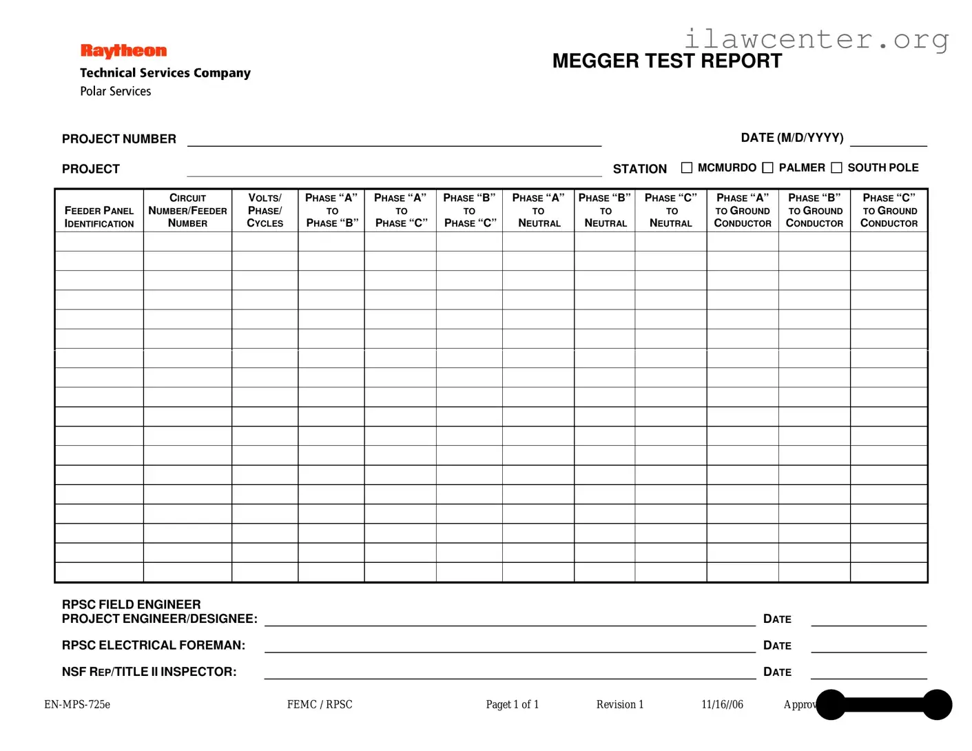
What information is included in the Megger Test form?

The Megger Test form includes essential details such as the project number, project station, date, feeder panel identification, circuit number, and voltage specifications. It also lists the insulation resistance readings between various phases and neutral, as well as to ground. This information is crucial for assessing the safety and reliability of the electrical system.

Why is the Megger Test important?

This test is vital for ensuring electrical safety and compliance with industry standards. By identifying potential insulation failures, it helps prevent electrical shocks, equipment damage, and fire hazards. Regular testing contributes to the longevity and reliability of electrical installations.

Who conducts the Megger Test?

The test is typically conducted by qualified electrical engineers or technicians. These professionals have the necessary training and experience to perform the test accurately and interpret the results correctly. Their expertise ensures that the testing process is safe and effective.

What do the readings on the Megger Test form indicate?

The readings on the form indicate the insulation resistance between different phases and neutral connections, as well as to ground. Higher resistance values generally indicate better insulation quality. If the readings are low, it may signal insulation degradation, requiring immediate attention to avoid potential hazards.

How often should Megger Tests be performed?

The frequency of Megger Tests can depend on several factors, including the type of equipment, environmental conditions, and regulatory requirements. Generally, it is recommended to conduct these tests annually or during significant maintenance activities. However, more frequent testing may be necessary in harsh environments.

What should be done if the Megger Test results are unsatisfactory?

If the results indicate low insulation resistance, immediate action should be taken. This may involve further investigation to identify the cause of the failure. Repairs or replacements of the affected insulation may be necessary to ensure safety and compliance with electrical standards.

What is the role of the RPSC Field Engineer in the Megger Test process?

The RPSC Field Engineer plays a crucial role in overseeing the Megger Test process. They ensure that the test is conducted correctly, document the results accurately, and provide recommendations based on the findings. Their involvement is essential for maintaining safety and compliance throughout the testing process.

Common mistakes

Filling out the Megger Test form requires attention to detail, and mistakes can lead to significant issues down the line. One common error is neglecting to fill in the project number. This information is crucial for tracking the test results and linking them to the specific project.

Another frequent mistake is omitting the date. Without a clear date, it becomes challenging to establish a timeline for the tests conducted. This can complicate any future inspections or audits.

People often confuse the feeder panel identification with the circuit number. These are distinct pieces of information, and mixing them up can lead to inaccurate reporting and potential safety hazards.

When recording voltage, it is essential to specify the volts, phase, and cycles accurately. Failing to do so can result in misunderstandings about the electrical system's performance and safety levels.

Another common oversight is leaving out the readings for phase combinations. Each combination, such as phase “A” to phase “B,” must be documented. Incomplete data can hinder troubleshooting efforts if issues arise later.

Some individuals forget to include measurements for ground conductors. These readings are vital for ensuring that the grounding system is functioning properly and meeting safety standards.

It is also important to ensure that the RPSC field engineer and project engineer/designee sections are filled out completely. Missing signatures can lead to questions about the validity of the test results.

Another mistake is not providing the NSF representative's title when signing off on the form. This information helps clarify the authority of the person validating the test results.

People sometimes overlook the revision number on the form. Using an outdated version can lead to errors in compliance with current standards and practices.

Lastly, failing to double-check the entire form for accuracy before submission can result in multiple errors going unnoticed. A thorough review can save time and prevent complications in the future.

Documents used along the form

When conducting electrical tests such as the Megger Test, several other forms and documents may accompany the main report. Each of these documents serves a specific purpose, ensuring that all aspects of the testing process are documented and compliant with safety and regulatory standards. Below is a list of commonly used forms in conjunction with the Megger Test form.

  • Test Equipment Calibration Log: This document records the calibration status of the testing equipment used. It ensures that all tools are functioning correctly and have been calibrated according to industry standards.
  • Safety Inspection Checklist: This checklist outlines safety measures taken before conducting the test. It includes verifying personal protective equipment (PPE) and ensuring that the testing area is safe for personnel.
  • Pre-Test Inspection Report: This report details the condition of the electrical system before testing begins. It includes observations about any visible issues that may affect test results.
  • Test Procedure Document: This document outlines the specific procedures to be followed during the Megger Test. It serves as a guide for technicians to ensure consistency and accuracy in testing.
  • Post-Test Analysis Report: After testing, this report summarizes the findings and any anomalies detected. It helps in understanding the condition of the electrical system and any necessary follow-up actions.
  • Maintenance Log: This log records any maintenance activities performed on the electrical system. It provides a history of repairs and upgrades, which can be useful for future testing and evaluations.
  • Incident Report Form: If any accidents or safety incidents occur during testing, this form documents the details. It is crucial for compliance and for implementing any necessary safety improvements.
  • Final Test Report: This comprehensive document includes all test results, analyses, and recommendations. It serves as the final record of the testing process and is often required for regulatory compliance.

Each of these documents plays a vital role in the overall testing process, ensuring that the Megger Test is conducted safely, accurately, and in compliance with relevant standards. Proper documentation not only aids in immediate evaluations but also contributes to long-term safety and reliability in electrical systems.

Similar forms

The Megger Test form serves a specific purpose in documenting electrical testing results. However, several other documents share similar characteristics and functions. Below is a list of eight such documents, highlighting their similarities with the Megger Test form.

  • Electrical Inspection Report: Like the Megger Test form, this document provides detailed information about electrical systems, including voltage readings and compliance with safety standards. It often includes inspector signatures and dates, ensuring accountability.
  • Test and Tag Report: This report is used to document the testing of electrical appliances and equipment. Similar to the Megger Test form, it records test results, identifies equipment, and includes the date of testing and the technician's information.
  • Commissioning Report: This document outlines the results of commissioning activities for new electrical systems. It shares the structured format of the Megger Test form, detailing tests performed, results, and responsible personnel, ensuring that systems meet specified performance criteria.
  • Preventive Maintenance Report: This report tracks maintenance activities on electrical equipment. It resembles the Megger Test form in its organized layout, documenting the date, tasks performed, and results, thereby facilitating ongoing system reliability.
  • Quality Assurance Report: Used in various industries, this document ensures that products or systems meet quality standards. It parallels the Megger Test form by providing a clear record of inspections, tests, and outcomes, often including signatures for verification.
  • Safety Audit Report: This document assesses compliance with safety regulations in electrical installations. Similar to the Megger Test form, it captures findings, recommendations, and responsible parties, thus promoting safety in electrical operations.
  • Field Service Report: This report is generated after a technician completes work on electrical systems. It shares the same structured approach as the Megger Test form, detailing services performed, findings, and technician information, ensuring transparency in service delivery.
  • Installation Verification Report: This document confirms that electrical installations have been completed according to specifications. Like the Megger Test form, it includes detailed measurements, compliance checks, and the signatures of responsible engineers, ensuring accountability in the installation process.

Dos and Don'ts

When filling out the Megger Test form, it is important to follow specific guidelines to ensure accuracy and clarity. Below is a list of things you should and shouldn't do.

  • Do ensure all project details are filled in completely, including project number and station.
  • Do accurately record the voltage, phase, and cycles for each test conducted.
  • Do double-check all entries for any potential errors before submission.
  • Do sign and date the form where required to validate the report.
  • Don't leave any fields blank; incomplete information can lead to misunderstandings.
  • Don't use abbreviations or shorthand that may not be universally understood.
  • Don't forget to include the names and titles of all individuals involved in the testing.
  • Don't submit the form without a final review to catch any mistakes.

Misconceptions

Misconceptions about the Megger Test can lead to confusion and misinterpretation of results. Here are six common misconceptions:

  1. The Megger Test is only for new installations. Many believe that this test is only necessary for new electrical systems. In reality, it is essential for both new and existing installations to ensure ongoing safety and performance.
  2. All Megger tests are the same. Some think that all Megger tests provide identical information. However, different tests measure various aspects of insulation resistance, and the results can vary significantly based on the specific test parameters.
  3. A high resistance reading is always good. While a high resistance reading typically indicates good insulation, it is not a definitive measure of system health. Other factors, such as environmental conditions and equipment age, can affect performance.
  4. The Megger Test can replace other testing methods. Some individuals assume that the Megger Test is a standalone solution. It should be part of a comprehensive testing strategy that includes other methods for a complete assessment of electrical systems.
  5. Results from the Megger Test are always easy to interpret. Many believe that interpreting the results is straightforward. In fact, understanding the implications of the readings requires expertise and knowledge of the specific system being tested.
  6. Once a Megger Test is passed, no further testing is needed. This misconception leads to complacency. Regular testing is crucial for maintaining system integrity, as conditions can change over time.

Understanding these misconceptions can help ensure that the Megger Test is used effectively and that electrical systems remain safe and reliable.

Key takeaways

When filling out and using the Megger Test form, consider the following key takeaways:

  • Accurate Information: Ensure all project details, such as project number and station, are correctly entered.
  • Clear Identification: Clearly identify the feeder panel and circuit numbers to avoid confusion during testing.
  • Voltage Specifications: Record the voltage, phase, and cycles accurately to ensure proper testing conditions.
  • Phase Testing: Document the resistance measurements between phases and to ground thoroughly.
  • Signatures Required: Obtain signatures from the RPSC field engineer and project engineer to validate the report.
  • Compliance: Follow all safety and compliance protocols during testing to protect personnel and equipment.
  • Review Process: Before final submission, review all entries for accuracy and completeness to ensure reliable results.

By adhering to these guidelines, you can effectively complete the Megger Test form and ensure accurate reporting of your electrical tests.